- 您现在的位置:买卖IC网 > Sheet目录364 > SSL3250AHN/C1,528 (NXP Semiconductors)IC LED DRVR PHOTO FLASH 16-HVQFN
�� �
�
�NXP� Semiconductors�
�SSL3250A�
�Photo� flash� dual� LED� driver�
�8.3.4� Flash� mode�
�The� Flash� mode� allows� the� main� LED� to� be� used� at� high� LED� current� setting.� The� Flash�
�mode� current� can� be� set� up� to� 500� mA� in� both� the� I� 2� C� and� Direct� enable� mode.�
�In� I� 2� C� mode,� the� current� is� defined� by� entering� a� value� between� a� minimum� of� 12� and� a�
�maximum� of� 31� in� the� current� control� register.� The� external� resistor� R_FL� can� be� used� to�
�scale� down� the� set� current.� This� can� be� used� in� the� application� to� enable� TxMasking� as�
�described� in� Section 8.3.6� .� The� current� in� the� main� LED� is� defined� using� Equation 3� .�
�When� not� using� the� R_FL� resistor,� assume� a� resistor� value� of� 50� k� Ω� in� the� equation.�
�Entering� Flash� mode� can� be� done� either� by� using� the� STRB� pin� or� the� FLASH_STRB� bit� in�
�Flash� Strobe� register� 02h.� The� duration� of� the� flash� can� be� determined� by� a� timer,� STRB�
�triggering� or� by� a� time-out.� The� flash� timing� is� given� by� Equation 3� and� in� Section 8.4.2� .�
�I� LED� =� ---------------� � (� 35� mA� +� 15� mA� � Register� )�
�50� k� Ω�
�R� R� _� FL�
�(3)�
�When� using� the� Direct� enable� mode,� the� flash� current� can� be� defined� by� an� external�
�resistor� connected� to� the� R_FL� pin.� The� current� in� the� main� LED� is� defined� using�
�Equation 4� .� When� not� using� the� current� set� resistor,� the� flash� current� will� be� set� to� a�
�default� level� of� 500� mA.� The� default� current� is� equal� to� connecting� an� external� current� set�
�resistor� of� 50� k� Ω� .� Entering� Flash� mode� in� Direct� enable� mode� can� be� done� using� the� EN1�
�and� EN2� pins.� The� LED� will� stay� on� in� Flash� mode� for� as� long� as� the� enable� pins� are� set� to�
�Flash� mode,� but� is� limited� to� 820� ms� maximum� by� the� time-out� timer.�
�I� LED� =� ---------------� � 500� mA�
�50� k� Ω�
�R� R� _� FL�
�(4)�
�When� no� external� current� set� resistor� is� used,� the� R_FL� pin� can� be� left� unconnected� but� is�
�preferably� connected� to� VIN.� Never� connect� the� R_FL� pin� to� GND� as� this� will� cause�
�unnecessary� reference� currents� to� flow� to� GND.�
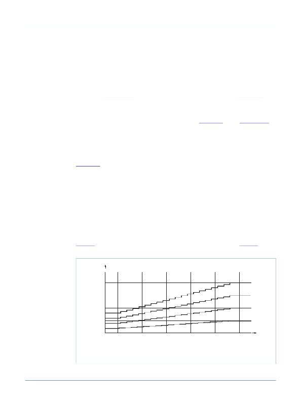
�Figure 7� illustrates� the� Flash� mode� current� setting� equation� for� I� 2� C,� while� Figure 8�
�illustrates� the� Flash� mode� current� setting� equation� for� the� Direct� enable� mode.�
�600�
�I� LED� (mA)�
�500�
�375�
�250�
�215�
�161�
�125�
�110�
�55�
�0�
�No�
�Resistor�
�66� .� 7�
�100�
�200�
�0�
�12�
�16�
�20�
�24�
�28�
�32�
�Register�
�Flash� current� using� I� 2� C� mode�
�Value� (k� Ω� )�
�014aaa366�
�SSL3250A_5�
�Fig� 7.�
�Flash� mode� LED� current� in� I� 2� C� mode�
�?� NXP� B.V.� 2009.� All� rights� reserved.�
�Product� data� sheet�
�Rev.� 05� —� 16� December� 2009�
�9� of� 26�
�发布紧急采购,3分钟左右您将得到回复。
相关PDF资料
SST25LF020A-33-4C-QAE-T
IC FLASH SER 2MB 33HZ SPI 8WSON
SST25VF010A-33-4I-QAE-T
IC FLASH SER 1MB 33MHZ SPI 8WSON
SST25VF016B-50-4C-S2AF-T
IC FLASH SER 16M 50MHZ SPI 8SOIC
SST25VF020-20-4C-QAE-T
IC FLASH SER 2MB 20MHZ SPI 8WSON
SST25VF020B-80-4C-QAE-T
IC FLASH SER 2MB 80MHZ SPI 8WSON
SST25VF032B-66-4I-S2AF
IC FLASH SER 32M 66MHZ SPI 8SOIC
SST25VF040B-50-4C-ZAE
IC FLASH SER 4MB 80MHZ SPI 8CSP
SST25VF040B-80-4I-QAE
IC FLASH SER 4MB 80MHZ SPI 8WSON
相关代理商/技术参数
SSL3252
制造商:PHILIPS 制造商全称:NXP Semiconductors 功能描述:Smart, simple solutions for the 12 most common design concerns
SSL3252UK/C2,515
功能描述:LED照明驱动器 Photo flash LED driver RoHS:否 制造商:STMicroelectronics 输入电压:11.5 V to 23 V 工作频率: 最大电源电流:1.7 mA 输出电流: 最大工作温度: 安装风格:SMD/SMT 封装 / 箱体:SO-16N
SSL33
功能描述:肖特基二极管与整流器 Low VF 3Amp 30v SMD Schottky Rect RoHS:否 制造商:Skyworks Solutions, Inc. 产品:Schottky Diodes 峰值反向电压:2 V 正向连续电流:50 mA 最大浪涌电流: 配置:Crossover Quad 恢复时间: 正向电压下降:370 mV 最大反向漏泄电流: 最大功率耗散:75 mW 工作温度范围:- 65 C to + 150 C 安装风格:SMD/SMT 封装 / 箱体:SOT-143 封装:Reel
SSL33 R6
制造商:SKMI/Taiwan 功能描述:Diode Schottky 30V 3A 2-Pin SMC T/R
SSL34
功能描述:肖特基二极管与整流器 Low VF 3Amp 40v SMD Schottky Rect RoHS:否 制造商:Skyworks Solutions, Inc. 产品:Schottky Diodes 峰值反向电压:2 V 正向连续电流:50 mA 最大浪涌电流: 配置:Crossover Quad 恢复时间: 正向电压下降:370 mV 最大反向漏泄电流: 最大功率耗散:75 mW 工作温度范围:- 65 C to + 150 C 安装风格:SMD/SMT 封装 / 箱体:SOT-143 封装:Reel
SSL34 R6
制造商:SKMI/Taiwan 功能描述:Diode Schottky 40V 3A 2-Pin SMC T/R
SSL3401HN/1Y
制造商:NXP Semiconductors 功能描述:SSL3401HN/HVQFN32/REEL13DP//1 - Tape and Reel
SS-L3TQ100-SXA
制造商:Microsemi Corporation 功能描述:EXTENDER FOR A54SX32A-FTQ100 - Trays